Showing posts with label rf. Show all posts

Monday, September 01, 2014

Talking SDR with Robert Ghilduta and Balint Seeber

As usual, the DEF CON Wireless Village put on an excellent program this year at DEF CON 22. In addition to the fantastic Wireless CTF contest, the village put together an impressive schedule of talks worthy of a much larger room.

Among the speakers lined up by the village were Balint Seeber of Ettus Research, Robert Ghilduta of Nuand, and myself of Great Scott Gadgets. Since the three of us were in the same place at the same time, we sat down for a long panel discussion on Software Defined Radio. Thanks to the Wireless Village crew and Adrian Crenshaw, you can now watch video of the conversation.

I'm looking forward next year's Wireless Village. Hopefully with a larger venue for DEF CON 23, the village will have space to seat all of the people who want to attend the events there.

Saturday, October 26, 2013

Appearance on The Amp Hour

In case further evidence is needed to demonstrate that I am a terrible blogger, I submit this: I had a wonderful time as a guest on Episode 161 of The Amp Hour and forgot to mention it here for nearly eight weeks! We discussed HackRF, Daisho, Ubertooth, wireless security, and how I came to the world of open source hardware from a background in information security. Thanks for having me on the show, Chris and Dave!

Tuesday, January 08, 2013

Funtenna!

I just watched Hacking Cisco Phones: Just because you are paranoid doesn't mean your phone isn't listening to everything you say, an excellent presentation by Ang Cui and Michael Costello at 29C3. I particularly liked that they coined the term "funtenna" to describe the potential capability of malware using the off-hook switch in a VoIP phone as an antenna to transmit data over RF.

I appreciate that they credited me with the idea, but I would like to set the record straight. I met Ang and Michael at a Cyber Fast Track event a couple months ago, and they approached me with the idea of exfiltrating data from the phone by toggling a GPIO pin on the embedded CPU at radio frequencies. My only contribution was looking at the hardware and suggesting that the wire extending to the off-hook switch was probably the best candidate antenna for the hack.

Although it hasn't been implemented yet, I think the idea has merit. I don't know how fast a GPIO pin can be toggled on the platform, but the CPU operates at something like 800 MHz. That makes it very likely that the maximum GPIO toggle rate is at least in the tens of MHz, maybe even over 100 MHz. I don't know the resonant frequency of the wire extending to the off-hook switch, but it is probably a few hundred MHz. If my guesses are close, then it is likely that the funtenna could be used to transmit data a short distance, perhaps through a wall or two. It isn't a very good radio, but it should work to some extent. Even a short range wireless transmission is very interesting when it originates from unmodified hardware not intended for wireless operation.

With Ang and Michael's approval, I would like to formalize the definition of "funtenna" a bit: A funtenna is an antenna that was not intended by the designer of the system to be an antenna, particularly when used as an antenna by an attacker. In the case of the Cisco phone, the funtenna could be used to transmit data from the phone. In certain systems, it may be possible to use a funtenna to receive radio signals as well. (I even know of some people working on a way to inject data into an untouched device using nothing but a high power radio signal; it is a very limited capability but theoretically possible.) The field of emission security studies unintentional radio emissions that leak data, and I would call any radiating element (a cable with poor shielding, for example) that leaks useful or sensitive information a funtenna.

Whenever I crack open an electronic device for the first time, I now look for potential funtennas. Maybe you will too. :-)

Friday, October 26, 2012

The ToorCon 14 Badge

I designed an electronic badge for ToorCon again this year. It features a CC1111 sub-1 GHz wireless transceiver IC with USB connectivity. This chip has the same radio as the CC1110 in the popular IM-Me. While the badge is certainly hackable hardware-wise, I hoped that it would allow people to explore radio applications without having to heat up any soldering irons.

The ToorCon 14 Badge shipped with RfCat firmware and a USB bootloader installed, so conference attendees were able to start experimenting with just a USB cable, a laptop, and the RfCat software. Although I am a fan of software defined radio, sometimes a wireless transceiver IC is all you need to do some interesting things, and RfCat is the easiest way I know to get started.

The badge is designed to be similar to and firmware compatible with the CC1111 EMK (aka "Don's Dongle"), but it has a few extra goodies. Most notably, it shipped with RfCat firmware and CC Bootloader installed. It also features a GoodFET compatible programming header and a row of test points that would have been compatible with the GIMME had I measured correctly. (Oops! Aren't you glad there is a USB bootloader?) The badge also has an option to install an external antenna connector, allowing better performance across the whole frequency range of the CC1111 than previous designs.

I held a badge hacking contest and was happy to see several people working on interesting ideas at the con. One group blew everyone else away: the Root the Box team built a multi-user wireless chat system. They implemented their own network protocol, user interface, and even HTTP tunneling from the ground up using RFCat's rflib Python library. (in two days!) Check out my video of the demonstration they gave me. They even posted the source code for their winning entry.

These were the same guys who won the ToorCon 13 badge hacking contest by implementing a simple game with 2.4 GHz wireless connectivity. Check out their Root the Box CTF event coming up in January!

There were a few extra badges made. Look for them to go on sale soon at HakShop and Ada's Technical Books.

Thursday, October 25, 2012

Announcing the HackRF Beta

Jared Boone and I had the honor of presenting the keynote at ToorCon 14 over the weekend. In our talk, HackRF: A Low Cost Software Defined Radio Platform, we described our project to build a low cost, open source, wideband, portable Software Defined Radio peripheral. You can watch video of the presentation or download the slides.

In addition to introducing HackRF to the ToorCon audience, we announced the HackRF beta test program. Thanks to DARPA's Cyber Fast Track (CFT) program, we are able to build a few hundred HackRF Jawbreakers and will distribute them to ToorCon attendees as soon as they are completed (hopefully around December). Each attendee of ToorCon 14 (and also the recent GNU Radio Conference) received a unique beta invitation code that can be redeemed for a Jawbreaker as soon as the hardware is ready to ship.

Jared and I are very excited to be able to give away so many beta units. I'm not sure if any open source hardware project has had such a well funded beta program, but we think that giving away hardware in exchange for feedback (and hopefully some code) is a good trade in keeping with open source ideals.

If you have an invitation code, look for an announcement on the HackRF page around December telling you how to redeem your code for a Jawbreaker. I know there are many of you out there who wish you had an invitation code, and I'm sorry that our funding for the beta program is finite! The redemption system, once it is live, will include a way to sign up for a waiting list if you do not have a code. There will probably be some extra beta units that we will distribute to as many on the waiting list as we can.

My hope for the beta program is to validate HackRF Jawbreaker, resulting in a well-tested open source design that anyone can build or modify. I also plan to release a commercial HackRF product (similar to Jawbreaker) that will be available for purchase after the beta.

Thanks for all the kind words of support at ToorCon and since!

Wednesday, October 17, 2012

Programming Pink Pagers in Style

After two and a half years of programming the IM-Me by soldering wires to the test points in the battery compartment, I finally got around to making a GoodFET/IM-Me spring pin adapter. I call it GIMME. Now I can install my spectrum analyzer application or any other firmware onto an IM-Me by simply removing the batteries and pressing the GIMME against the test points while the attached GoodFET does all the tricky stuff. GIMME is designed with KiCad. You can find the design files in the contrib directory of the GoodFET repo.

To mark this occasion, I decided it was high time to post the video from my talk with Travis Goodspeed at ToorCon 12, Real Men Carry Pink Pagers. It was probably the most fun I've ever had giving a talk at a hacker con. Maybe it was the song. Maybe it was the bourbon in pink shot glasses. Maybe it was the total lack of preparation resulting from Travis injuring himself the day before. Maybe it was the ridiculous T-shirt Nick DePetrillo made me wear. (I still haven't figured out how to get him back. I don't believe it is possible to embarrass the man.)

With ToorCon 14 coming up, I decided to have several GIMME PCBs made to give away. If you see me at the con this weekend and would like one, just ask. I also took it upon myself to make some GoodFET41 boards since Travis won't be around being his usual Johnny Appleseed of open source hardware. Plus, I will have a GIMME and GoodFET available to borrow, so bring that IM-Me that has been sitting in a drawer with factory firmware!

Monday, October 01, 2012

HackRF Jawbreaker

Last week at the GNU Radio Conference I showed off Jawbreaker, the first unified HackRF board. I had assembled it just prior to leaving for the conference. It is completely built (including a couple of minor corrections), and I am about three-quarters of the way through validating the design.

Jawbreaker integrates three separate designs into a single circuit board, making it smaller and easier to handle. Since my previous post, I tested multiple wideband front-end designs, eventually settling on one called Licorice. Jawbreaker is a combination of Licorice, Lemondrop, and Jellybean into a single USB-powered software radio transceiver peripheral designed to operate from 30 MHz to 6 GHz.

This week I plan to finish validating the design and ordering PCBs of the next (likely final) revision. While I validate and revise the hardware design, Jared is hard at work on a USB driver for the LPC43xx microcontroller on the board. Prior to combining the three boards into Jawbreaker, I successfully tested both transmit and receive paths from the antenna all the way to the microcontroller, but the "last mile" USB communication from the microcontroller to the host computer was still incomplete.

I had planned to bring a finished Jawbreaker for everyone attending my software radio workshop at ToorCon San Diego later this month, but unfortunately it doesn't look like I'll have enough working units by then. Instead I will provide alternative hardware that will fully enable everyone to participate in the workshop exercises, and I will send Jawbreakers to the attendees when they are finished later. (There are still a couple of seats open in the workshop, by the way.)

A puzzling feature you might have noticed on Jawbreaker is the integration of a PCB trace antenna for the 900 MHz band. Although the board is designed for operation over a much wider frequency range, this antenna allows people to start experimenting with the board in the 900 MHz band immediately without any antennas, connectors, or anything at all other than a USB cable and computer. I want it to be easy for people to get started with the device because Jawbreaker is intended as the beta test platform for the HackRF project. We plan to assemble quite a few Jawbreakers and will distribute them to beta testers in the coming weeks. Beta hardware availability will be announced at ToorCon.

Friday, June 22, 2012

Introducing HackRF

I'd like to take a moment to properly introduce the project that is consuming most of my time this year: HackRF, a software radio peripheral. Software radio or Software Defined Radio (SDR) is the application of Digital Signal Processing (DSP) to radio waveforms. It is analogous to the software-based digital audio techniques that became popular a couple of decades ago. Just like a sound card in a computer digitizes audio waveforms, a software radio peripheral digitizes radio waveforms. It's like a very fast sound card with the speaker and microphone replaced by an antenna. A single software radio platform can be used to implement virtually any wireless technology (Bluetooth, GSM, ZigBee, etc.).

Digital audio capabilities in general purpose computers enabled a revolution in the sound and music industries with advances such as hard disk recording and MP3 file sharing. Today's computers are fast enough to process radio waveforms in similar ways, and the radio communications industry is going through the same sorts of changes. One critical advance has yet to take place, and that is the availability of low cost tools enabling any computer user to take part in the revolution.

HackRF project goals:

  • transmit and receive
  • operating frequency: 100 MHz to 6 GHz
  • maximum sample rate: 20 Msps
  • resolution: 8 bits
  • interface: High Speed USB
  • power supply: USB bus power
  • portable
  • open source hardware and software
  • low cost

There have been some exciting developments in the world of low cost software radio hardware in recent months, but the HackRF project will go much further. A key advance will be the ability to transmit as well as receive radio signals, and HackRF will also enable operation at higher frequencies, including the popular 2.4 GHz band. Most importantly, HackRF is an open source project, so people will always be able to use and modify the hardware design and software in the future. We are being very careful to only use electronic components with published documentation (no NDAs!) and to avoid software libraries without open source licenses. This means more work for us, but we think that it will be worth it in the long run.

Speaking of us, I should mention that I have some help on this project. My primary partner in this effort is Jared Boone of ShareBrained Technology (who has already written a bit about some of our development challenges). We've had some additional help from a few other people who hang out in #hackrf on chat.freenode.net, notably Benjamin Vernoux.

Ultimately, the HackRF project aims to produce a single device that meets the goals above, but right now it consists of multiple development boards that connect together. The microcontroller, USB interface, and power supply are on the largest board called Jellybean. The Intermediate Frequency (IF) transceiver, Analog to Digital Converter (ADC), Digital to Analog Converter (DAC), and clock generator are on a board called Lemondrop. Most recently, a wideband front-end called Lollipop is being tested. HackRF is based on a dual conversion architecture with a high IF (between 2.3 and 2.7 GHz), allowing us to take advantage of the excellent capabilities (per size, cost, and power consumption) of a wireless transceiver IC.

I have used software radio techniques for wireless security research for years, and I teach a workshop each year at ToorCon San Diego to help more people in the information security community become familiar with the technology. Both for my own use and to promote wireless security research, I have long dreamed of building a low cost, portable platform. Now, with support from DARPA's CFT program, I am finally able to make this project a reality.

Personally, I want a single device that can fit in my laptop bag, that doesn't require a bulky power supply, and that I can use to hack on whatever wireless systems I encounter. I'm hoping it will be about the size of a portable USB hard drive, and it will probably end up with a retail price in the neighborhood of $300, higher than technology-specific solutions like Ubertooth One but much less than any software radio transceiver on the market today.

The project is going well, and we are likely to meet most or all of the goals. If there is one we miss, it will probably be the operating frequency range. 100 MHz to 6 GHz is quite ambitious! At the very least, we will produce a platform that allows operation over a wide range including both the 2.4 GHz and 900 MHz bands.

HackRF is being developed on github. Documentation is coming together slowly on the wiki.

Thursday, August 18, 2011

Spread Spectrum Clock Generation, Emission Security, and You

The following is a transcript, more or less, of a short talk I gave at ToorCon Seattle 2011. There was no video made of the presentation, so I'm doing this instead. The talk was a preview of some research into how spread spectrum clock generation affects the risk of eavesdropping on unintentional Radio Frequency (RF) emanations from electronic devices.

Probably half of you are sick of hearing me talk about Project Ubertooth and the other half will be, so today I'm talking about something completely different: clocks. Not the kind of clocks you hang on a wall but periodic electrical signals that drive the timing of digital electronics and the circuits that produce those clock signals. Every digital electronic device has a clock. When you talk about your fancy, new, 3.0 GHz computer, you are referring to the clock frequency.

A traditional clock signal looks like this. The top graph shows how the voltage changes over time. The timing is fairly consistent. If you plot the signal in the frequency domain, the bottom graph, you get a sharp spike at the clock frequency. Note that I am ignoring harmonics here and have zoomed in on the region around the fundamental clock frequency.

About twenty years ago, some guys in Kentucky had this idea to modulate the frequency of a clock over time. They called the technique Spread Spectrum Clock Generation (SSCG). A spread spectrum clock signal looks something like this. The frequency of the signal varies over time. If you look at the signal in the frequency domain, the bottom graph, you see a plateau over a range of frequencies instead of a narrow spike. (If you are familiar with spread spectrum communication systems, note that I'm talking about something only vaguely related.)

SSCG became popular, first with PC manufacturers and more recently for other electronic devices. The technique is used for one and (as far as I know) only one reason: to make it easier to pass electromagnetic compatibility (EMC) testing required by the FCC and other regulatory bodies around the world. EMC regulations are intended to limit RF emissions of electronic devices in order to avoid harmful interference to radio systems and other neighboring electronics. SSCG doesn't do anything to reduce the radiated power of such emissions; it simply shifts their frequencies around so the EMC test equipment doesn't register too high a power level at any one frequency. The electronics manufacturers are playing a shell game with their clock frequencies in order to evade detection.

A few of you may have seen a recent blog post of mine, If it isn't open, it didn't happen. In it I proposed a citation boycott: scientific works not open to the public shouldn't be considered to have been published at all and should not be cited. Well, I'm about to break my own boycott. Actually I am declaring an exception, an exception for ridicule: It is okay to cite a non-open scientific work if the citation is made for the purpose of ridiculing said work.

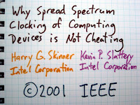
About ten years ago, there was growing concern that SSCG might be bad for electromagnetic compatibility. It was clear that the practice resulted in electronic devices that produced higher overall radiated emissions. Plus people were starting to get the idea that wideband interference from devices with spread spectrum clocks could be worse for radio signals than narrowband interference from traditional clocks, even when comparing the two at the same radiated power level. In response, Harry G. Skinner and Kevin P. Slattery of Intel published a short paper called Why Spread Spectrum Clocking of Computing Devices is Not Cheating. It is a truly awful paper. The authors, Intel, and the IEEE should all be embarrassed to have their names on it. It features bad theory, bad analysis, bad experimentation - just about everything that could be wrong with scientific literature is evident in this biased piece of garbage. I will limit myself to pointing out just one fallacy in detail.

The authors claim that concern over the wide bandwidth of SSCG emissions is misplaced because the emissions aren't actually wide at all. If you configure your test equipment the way the FCC requires, then the emissions appear to cover a wide range of frequencies. This doesn't tell the whole story, they say.

They propose looking at the emissions over shorter windows of time. A quick snapshot would show a signal that is actually narrowband, similar to the frequency spike produced by a traditional clock. Subsequent snapshots show that the signal is still narrow but shifted to different frequencies. (Click the graph for sophisticated and professional-looking animation.)

To some extent, the authors are correct, but they conveniently leave out a rather important detail. If you look at the signal the way the FCC requires, you see a wideband emission consisting of power at various frequencies under the regulatory limit.

If, however, you look at the signal the way the authors propose, you see a narrowband emission that exceeds the regulatory limit. You can't have it both ways, guys. You either show that the signal is wide, averaged over a range of frequencies, or you reveal that the radiated power exceeds the legal limit and that your spread spectrum clock is exploiting a loophole in the peculiarities of the FCC test specification.

Amazingly enough, this unscientific trash seems to be pretty much the last word on the subject. I think it is time for fresh eyes to look at spread spectrum clock generation. I've been looking at it for a little while and have developed two hypotheses.

Hypothesis #1: The increasing prevalence of spread spectrum clock generation is detrimental to the operation of a wide variety of radio systems. SSCG is becoming popular not just in PCs but in smartphones, LCD panels, and other high speed electronic devices. It is required by interface standards such as SATA and SuperSpeed USB. As more and more of these devices are deployed (probably billions per year), the noise floor is raised for everyone trying to use the radio spectrum. This hypothesis is hard to test, so I'm skipping it.

Hypothesis #2: Devices with spread spectrum clock generation are more susceptible to eavesdropping than those without. I'm talking about emission security, the problem that electronic devices tend to unintentionally emit radio signals that can reveal otherwise secret information. Someone might be able to discover the password for your bank account, for example, by monitoring radio signals produced by your computer.

There are two reasons I think SSCG results in an increased susceptibility to eavesdropping. The first is that SSCG devices produce stronger emissions. This is almost by definition: the reason SSCG is deployed in the first place is to get away with emissions stronger than those that would be permitted from a device without SSCG. The second is that SSCG emissions feature spread spectrum signatures that make it easier for an eavesdropper to pick the signals out of the noise. This will be a little more difficult to demonstrate, but techniques from the field of digital radio communication could be applied to the problem.

In the coming months I will attempt to test hypothesis #2. I'll start by analyzing the waveforms produced by popular spread spectrum clock generator integrated circuits, and then I will apply the knowledge gained to the problem of eavesdropping on consumer electronic devices. If you are interested in helping with this research, I would love to hear from you!

Thursday, February 24, 2011

Ubertooth spectrum analyzer

I took a break from hardware and manufacturing concerns tonight and sat down to write some code. I probably should have worked on the USB bootloader, but instead I wrote a simple spectrum analysis function for the Ubertooth platform. Similar to other transceiver IC spectrum analyzers (like my IM-Me implementation), it tunes its receiver to one frequency at a time and records the received signal strength before hopping to the next frequency.

For now I'm just dumping a table of values to a file and plotting it with gnuplot. In the future perhaps a more sophisticated user interface could be built, maybe integrating with Mike Kershaw's Spectrum Tools or something like that. In this plot, you can see a busy 802.11g network on channel 1 (centered at 2412 MHz) and some Bluetooth traffic (a device performing an inquiry scan) throughout the band.

While testing this, I tried pushing the limits of the CC2400's tuning range for the first time. The device I tested functioned with its receiver tuned from 2268 to 2794 MHz. (The supported range is 2400 to 2483.) I didn't actually generate test signals to validate that it could see stuff throughout the entire range, but my guess is that it is usable across the whole tunable range but with degraded performance at the extremes.

The spectrum analysis code is available in the Ubertooth repository and will be included in the next release. Let me know if you do anything interesting with it. There are just a few days left to pick up one of the first batch of boards by making a pledge on Kickstarter.

Sunday, February 06, 2011

Project Ubertooth: Building a Better Bluetooth Adapter

Video of my presentation, Project Ubertooth: Building a Better Bluetooth Adapter, at ShmooCon 2011 is now online. You can download the entire video in high quality from shmoocon.org or watch it in your web browser. In the presentation, I demonstrated Ubertooth One, the world's first open source, widely available, low cost Bluetooth test tool, and I described my two year design journey starting as an electronics novice. This was one of the most fun talks I've ever given, and I want to thank ShmooCon for making it happen and everyone who attended for participating. I'm making the slides available, but, as is typical of my presentation slides, they really don't stand alone.

Shortly before the presentation, I was interviewed by Hak5. The interview covered a lot of ground and included quite a bit of discussion beyond the content of the presentation.

At ShmooCon I announced the start of a pledge period on Kickstarter to fund an initial production run of Ubertooth One boards, and the pledge goal was met in just four days! There is still time remaining in the pledge period for anyone who would like a board. Thank you to everyone who has pledged support!

Wednesday, February 02, 2011

first Bluetooth Low Energy packets

A package arrived today containing my first Bluetooth Low Energy equipment. Bluetooth Low Energy is a new wireless technology within the Bluetooth specification suite. It provides capabilities similar to Basic Rate Bluetooth, which has been around for ten years, but consumes less power while doing so. Consumer Bluetooth Low Energy products likely won't hit the market for a few months, but engineering development tools have recently become available.

This kit from Texas instruments contains a two small CC2540 development boards, one in the form of a keyfob and the other in a USB dongle form factor. For now I'm not interested in developing firmware for the CC2540. Frankly I'm annoyed that TI has chosen not to document the internal radio properly. Despite its limitations, however, this kit provides a quick and easy way to generate Bluetooth Low Energy wireless packets over the air, and I'm using it (so far just the keyfob) to help me develop Low Energy sniffing capability on the Ubertooth platform.

It only took a few minutes to tweak the Ubertooth code such that it would demodulate Bluetooth Low Energy packets properly, but I don't have much in the way of automated packet detection or decoding. Using a fairly crude method, I've searched through the demodulated bits to find the advertising packets transmitted by the keyfob. These are packets transmitted on one of only three advertising channels in an effort to locate another device to communicate with.

One of the key differences between Basic Rate and Low Energy is that Low Energy devices are able to locate each other and initiate communications using this advertising method much faster than Basic Rate devices ever could. Basic Rate devices waste a lot of power keeping connections alive; Low Energy devices will just tear down connections entirely and go to sleep knowing that they can wake up and find each other again very quickly. One of the reasons the method is fast is that advertising is only done on three channels, and that makes it easier for a passive observer to capture the process.

I've also captured the packets using a USRP. Glancing at the waveform and spectrogram, it is difficult to distinguish this packet from Basic Rate Bluetooth. I haven't written any GNU Radio code to demodulate the raw waveform, but I am replaying the recorded file through the USRP as a simple way to produce a repeatable test vector.

Monday, January 31, 2011

Ubertooth One on Kickstarter

At ShmooCon over the weekend, I gave the first public demonstration of Ubertooth One, a smaller and more powerful Ubertooth hardware platform. I also announced the beginning of a pledge period on Kickstarter that allows anyone to take part in the first production run of commercially available Ubertooth Ones. If you would like an Ubertooth One of your own, I encourage you to consider building one or making a pledge on Kickstarter. Thank you for your support and for helping to spread the word!

Tuesday, November 16, 2010

Ubertooth: first release

Tonight I uploaded the first release of Project Ubertooth, an open source wireless development platform that can be used for Bluetooth testing and research. This is a very preliminary release, but it includes the complete hardware design for Ubertooth Zero, firmware source code, and the host code needed to perform rudimentary Bluetooth sniffing as I demonstrated at ToorCon 12. Although you can download a project archive, I recommend using the Subversion repository so that you can easily keep up to date with the project as it develops.

The documentation is still a bit thin, but there are README files scattered about the project directories. The host code can be compiled with gcc on Linux. The firmware also can be compiled with a gcc toolchain (I have found the CodeSourcery package to be helpful) and can be flashed onto a board with lpc21isp. I've been using a slightly modified SparkFun FTDI Basic Breakout for this, but there are several serial programming devices that will work with lpc21isp.

Also in the repository is an early hardware design for Ubertooth One, the next generation board that I hope to have ready within a couple months. This is a more challenging design that will probably require a few revisions, so keep your expectations low if you try to build one based on the current layout.

Wednesday, October 27, 2010

Ubertooth Zero, a preview

Last weekend at ToorCon 12 I unveiled Project Ubertooth, something I've been working on for more than a year. The goal of the project is to produce a low cost 2.4 GHz wireless development platform suitable for Bluetooth sniffing (among other things). If you are familiar with previous work on Bluetooth monitoring, then you know that good tools are expensive. Commercial equipment costs $10,000 or more, and even the open source solution requires a hardware investment of at least $1000.

In my talk, Ubertooth Zero, a preview, I demonstrated Bluetooth sniffing for the first time with Ubertooth Zero, my first prototype hardware model. The platform is based on the Texas Instruments CC2400 wireless transceiver paired with NXP's LPC1758, an ARM microcontroller with USB. You can build an Ubertooth Zero for less than $50 in parts. The hardware design and host code are published in the svn repository at http://ubertooth.sourceforge.net/, and firmware will follow as soon as possible (probably a couple weeks). Everything is open source.

Over the coming weeks I'll be working on the next model, Ubertooth One, which I hope to have available in early 2011. It will be compatible with the Ubertooth Zero software but will have an improved RF front end, comparable to a Class 1 Bluetooth device. I hope to produce Ubertooth One commercially, making it available to those who don't want to solder 0402s, but rest assured that the product will remain fully open source. I'm also working on firmware, host software, and documentation so that the platform will be easier to build and use.

I would love to hear from you if you decide to build an Ubertooth Zero. Keep in mind that this is a preview release with much work still undone. So far I've built three working boards, one of which fetched $275 in Sunday night's ToorCon Foundation auction, supporting technology education in developing countries. I have three more that I hope to get working soon, and then I'll start work on Ubertooth One.

So far I have implemented only single channel Bluetooth monitoring. The device sits on a single channel and receives a small subset of packets from all Bluetooth devices in range (the target devices use frequency hopping, so they only transmit a small percentage of their packets on that particular channel). This is sufficient to provide a good survey of Bluetooth activity. With some work on software in the future, the platform should be capable of hopping along with a target, receiving every packet on that piconet. Once that is working, it should be possible to use the Ubertooth platform for raw frame injection, an important capability that has been out of reach of wireless security researchers since Bluetooth's introduction. The platform could also be used for several non-Bluetooth functions such as spectrum monitoring or 802.11 FHSS

ToorCon was a blast, as always. Thanks to everyone who attended the Software Defined Radio Workshop, Real Men Carry Pink Pagers, and the Ubertooth talk. Thanks to Travis for making our talk so much fun. Thanks to Dominic for making the trip from London. Thanks to George, Tim, and David for putting on a great con and making me feel so welcome. Thanks to all the friends, both old and new. Thanks(?) to Nick et al. for embarrassing the hell out of me. Thanks to Laen for running the DorkbotPDX PCB service. Most of all, thanks to Jared Boone who couldn't be at ToorCon but who has supported my effort to develop Project Ubertooth more than anyone.

Tuesday, March 16, 2010

a $16 pocket spectrum analyzer

ShmooCon was, once again, a fantastic experience this year. One of many highlights of this year's event for me was hacking on some radio devices with Travis Goodspeed in the hotel bar for hours on end. This included playing with the IM-Me that he brought. As soon as I got home I ordered one. I found mine for $15.99 and free shipping on eBay.

Since then I've written custom firmware to turn my IM-Me into a pocket spectrum analyzer, shown here displaying activity of a frequency hopping system at a grocery store. The only change I've made to the hardware is the addition of a ribbon cable in order to easily connect to a GoodFET for programming, but this is simply creating a permanent connection to the debug contact points that are already exposed in the battery compartment. I've followed Travis's advice on how to develop for the platform.

The software tunes the IM-Me's radio chip to one frequency at a time, uses the chip's RSSI measurement function, and plots the result as one column on the LCD. It sweeps across the whole screen (132 columns) several times per second, showing a contiguous range of radio frequency activity. The technique works quite well, although there are a few defects. Most notably, harmonics of the IM-Me's 26 MHz crystal show up as spurs on the display.

The frequency ranges supported by my device are 281 - 361, 378 - 481, and 749 - 962 MHz. This is about 50% more than the chip is advertised to support and covers quite a bit of interesting activity in the US including ISM, LMR, television, amateur bands, pagers, and mobile phones. The edges of the bands supported by other batches of chips may differ but probably not by much.

The software supports three bandwidth modes: wide (default), narrow, and ultrawide. Wide mode displays 26.4 MHz of bandwidth in 200 kHz increments. Narrow mode displays 6.6 MHz of bandwidth in 50 kHz increments. Ultrawide mode, shown here with some mobile phone activity, displays 88 MHz of bandwidth in 667 kHz increments.

The code is open and available here. I'd love to hear from you if you give it a try. Huge thanks to both Travis and Dave who did the hard reverse engineering work!

Update: The code has a new home at github.

Friday, February 05, 2010

ShmooCon live!

I'm giving a talk on Bluetooth keyboard security at ShmooCon this year. Live video of the talk will be provided. My talk will be at 3:00 PM EST on Saturday, February 6th in the Break It! track.

Tuesday, January 12, 2010

KillerBee on a budget

At ToorCon 11, Joshua Wright handed out a pre-release version of his KillerBee framework, a set of tools for analysis of 802.15.4 and ZigBee wireless networks.

KillerBee requires a particular hardware device, Atmel's AVR RZUSBSTICK, an inexpensive USB dongle with a programmable microcontroller. Many of the KillerBee functions require custom firmware (written by Joshua) to be flashed onto the stick. While most Atmel products feature In-System Programming (ISP) which can be done with a low-cost programming device, the RZUSBSTICK unfortunately only provides a JTAG header for programming, and the JTAG debugger/programmer costs about $300.

The good news is that ISP can be used to program the RZUSBSTICK. The bad news is that it requires some tricky soldering to get it working. With a little guidance from those who have gone before me and SparkFun's excellent surface mount soldering tutorials under my belt, I was able to attach a 10-pin ISP header to my RZUSBSTICK and successfully flash it with the KillerBee firmware.

There are two kinds of AVR ISP headers, a 6-pin and a 10-pin version. I chose the 10-pin variety because my programmer has a 10-pin connector, but a simple adapter can allow you to use either. Both varieties use the same 6 signals: GND, VCC, RESET, SCK, MISO, and MOSI. I connected them with colored wire (28 or 30 AWG wirewrap wire) as follows:

signalcolorheader pinsource
GNDblack4,6,8,10JTAG header pin 2
VCCred2JTAG header pin 4
RESETwhite5JTAG header pin 6
SCKpurple7AT90USB1287 pin 11
MISObrown9AT90USB1287 pin 13
MOSIorange1AT86RF230 pin 22

I ran all six wires through the unused holes of the (unpopulated) JTAG header in order to provide some strain relief. Those connections to the individual chip pins are fragile! From there I ran them across the back of the board to a 10-pin header glued to the end of the stick.

My serial programmer works great when connected to an on-board serial port on an old PC, but its bit-banging technique is incredibly slow (about 3 bits per second) and unreliable when connected to a USB/serial adapter. I believe that trying to use it via USB was the cause of death of an ATtiny85 while working on a previous project. Anyway, with a good serial port, AVRDUDE does a fine job programming the RZUSBSTICK over ISP:

avrdude -c ponyser -p usb1287 -P /dev/ttyS0 -U flash:w:kb-rzusbstick1.hex

Now to find some target devices. . .

Saturday, September 12, 2009

ToorCon workshop

I'll be running a software radio workshop at ToorCon in October. It will be similar to the workshop at ToorCamp but with more electricity and less volcanic ash! With a more pleasant environment and more structured lessons, a greater amount of material will be covered.

Friday, September 11, 2009

building an all-channel Bluetooth monitor

video (179M) of my presentation with Dominic Spill at ShmooCon 2009 has been posted.