Thursday, August 18, 2011

Spread Spectrum Clock Generation, Emission Security, and You

The following is a transcript, more or less, of a short talk I gave at ToorCon Seattle 2011. There was no video made of the presentation, so I'm doing this instead. The talk was a preview of some research into how spread spectrum clock generation affects the risk of eavesdropping on unintentional Radio Frequency (RF) emanations from electronic devices.

Probably half of you are sick of hearing me talk about Project Ubertooth and the other half will be, so today I'm talking about something completely different: clocks. Not the kind of clocks you hang on a wall but periodic electrical signals that drive the timing of digital electronics and the circuits that produce those clock signals. Every digital electronic device has a clock. When you talk about your fancy, new, 3.0 GHz computer, you are referring to the clock frequency.

A traditional clock signal looks like this. The top graph shows how the voltage changes over time. The timing is fairly consistent. If you plot the signal in the frequency domain, the bottom graph, you get a sharp spike at the clock frequency. Note that I am ignoring harmonics here and have zoomed in on the region around the fundamental clock frequency.

About twenty years ago, some guys in Kentucky had this idea to modulate the frequency of a clock over time. They called the technique Spread Spectrum Clock Generation (SSCG). A spread spectrum clock signal looks something like this. The frequency of the signal varies over time. If you look at the signal in the frequency domain, the bottom graph, you see a plateau over a range of frequencies instead of a narrow spike. (If you are familiar with spread spectrum communication systems, note that I'm talking about something only vaguely related.)

SSCG became popular, first with PC manufacturers and more recently for other electronic devices. The technique is used for one and (as far as I know) only one reason: to make it easier to pass electromagnetic compatibility (EMC) testing required by the FCC and other regulatory bodies around the world. EMC regulations are intended to limit RF emissions of electronic devices in order to avoid harmful interference to radio systems and other neighboring electronics. SSCG doesn't do anything to reduce the radiated power of such emissions; it simply shifts their frequencies around so the EMC test equipment doesn't register too high a power level at any one frequency. The electronics manufacturers are playing a shell game with their clock frequencies in order to evade detection.

A few of you may have seen a recent blog post of mine, If it isn't open, it didn't happen. In it I proposed a citation boycott: scientific works not open to the public shouldn't be considered to have been published at all and should not be cited. Well, I'm about to break my own boycott. Actually I am declaring an exception, an exception for ridicule: It is okay to cite a non-open scientific work if the citation is made for the purpose of ridiculing said work.

About ten years ago, there was growing concern that SSCG might be bad for electromagnetic compatibility. It was clear that the practice resulted in electronic devices that produced higher overall radiated emissions. Plus people were starting to get the idea that wideband interference from devices with spread spectrum clocks could be worse for radio signals than narrowband interference from traditional clocks, even when comparing the two at the same radiated power level. In response, Harry G. Skinner and Kevin P. Slattery of Intel published a short paper called Why Spread Spectrum Clocking of Computing Devices is Not Cheating. It is a truly awful paper. The authors, Intel, and the IEEE should all be embarrassed to have their names on it. It features bad theory, bad analysis, bad experimentation - just about everything that could be wrong with scientific literature is evident in this biased piece of garbage. I will limit myself to pointing out just one fallacy in detail.

The authors claim that concern over the wide bandwidth of SSCG emissions is misplaced because the emissions aren't actually wide at all. If you configure your test equipment the way the FCC requires, then the emissions appear to cover a wide range of frequencies. This doesn't tell the whole story, they say.
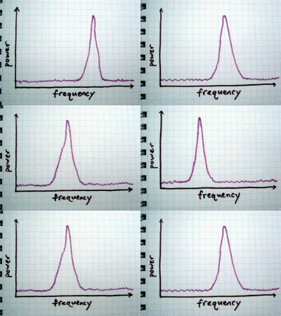
They propose looking at the emissions over shorter windows of time. A quick snapshot would show a signal that is actually narrowband, similar to the frequency spike produced by a traditional clock. Subsequent snapshots show that the signal is still narrow but shifted to different frequencies. (Click the graph for sophisticated and professional-looking animation.)

To some extent, the authors are correct, but they conveniently leave out a rather important detail. If you look at the signal the way the FCC requires, you see a wideband emission consisting of power at various frequencies under the regulatory limit.

If, however, you look at the signal the way the authors propose, you see a narrowband emission that exceeds the regulatory limit. You can't have it both ways, guys. You either show that the signal is wide, averaged over a range of frequencies, or you reveal that the radiated power exceeds the legal limit and that your spread spectrum clock is exploiting a loophole in the peculiarities of the FCC test specification.

Amazingly enough, this unscientific trash seems to be pretty much the last word on the subject. I think it is time for fresh eyes to look at spread spectrum clock generation. I've been looking at it for a little while and have developed two hypotheses.

Hypothesis #1: The increasing prevalence of spread spectrum clock generation is detrimental to the operation of a wide variety of radio systems. SSCG is becoming popular not just in PCs but in smartphones, LCD panels, and other high speed electronic devices. It is required by interface standards such as SATA and SuperSpeed USB. As more and more of these devices are deployed (probably billions per year), the noise floor is raised for everyone trying to use the radio spectrum. This hypothesis is hard to test, so I'm skipping it.

Hypothesis #2: Devices with spread spectrum clock generation are more susceptible to eavesdropping than those without. I'm talking about emission security, the problem that electronic devices tend to unintentionally emit radio signals that can reveal otherwise secret information. Someone might be able to discover the password for your bank account, for example, by monitoring radio signals produced by your computer.

There are two reasons I think SSCG results in an increased susceptibility to eavesdropping. The first is that SSCG devices produce stronger emissions. This is almost by definition: the reason SSCG is deployed in the first place is to get away with emissions stronger than those that would be permitted from a device without SSCG. The second is that SSCG emissions feature spread spectrum signatures that make it easier for an eavesdropper to pick the signals out of the noise. This will be a little more difficult to demonstrate, but techniques from the field of digital radio communication could be applied to the problem.

In the coming months I will attempt to test hypothesis #2. I'll start by analyzing the waveforms produced by popular spread spectrum clock generator integrated circuits, and then I will apply the knowledge gained to the problem of eavesdropping on consumer electronic devices. If you are interested in helping with this research, I would love to hear from you!

Wednesday, July 13, 2011

Discoverability is Not a Mitigating Factor

Four years after BlueSniff: Eve Meets Alice and Bluetooth by Dominic Spill and Andrea Bittau, people are still saying that Bluetooth vulnerabilities can be mitigated by turning off discoverability. If there is one thing that should have been learned from all of the Bluetooth security research done over the last few years, it is that a non-discoverable device is no safer than a discoverable one, but perhaps this message has been buried too deeply in technical presentations. Let me try to make this point clearer.

A discoverable Bluetooth device is one that is willing to respond to an inquiry, a single packet transmitted by any device looking for others. When you tell a device to "find new Bluetooth devices" it transmits a large number of inquiry packets and waits for responses. A discoverable device's inquiry response contains information including the device's address (BD_ADDR). This address can then be used by the inquirer to initiate a connection between the two devices.

Since most Bluetooth vulnerabilities can only be exploited once a connection is established, people used to recommend turning off discoverability. The reasoning was that, without a way to learn the target's address, an attacker would be unable to connect to the target and exploit any vulnerability. This idea that it is possible to keep a Bluetooth device address secret is completely wrong.

Turning off discoverability is like hiding the SSID of an 802.11 network. It prevents people from casually or accidentally connecting to your Bluetooth device. It might be worth doing for this reason alone, but I no longer recommend it as a security practice. Turning off discoverability does nothing to thwart skilled attackers. Worse, it creates a false sense of security and makes it harder for the good guys to notice that Bluetooth devices are in use.

A BD_ADDR is a 48 bit number (it's a MAC address) that is unique to a particular Bluetooth device. It consists of three sections, the 16 bit Non-Significant Address Part (NAP), the 8 bit Upper Address Part (UAP), and the 24 bit Lower Address Part (LAP). In order to connect to a target, an attacker needs only the UAP and LAP.

LAP sniffing is easy. Every Bluetooth packet contains the LAP in cleartext. Spill and Bittau showed how to sniff LAPs with a USRP for about $1000. Now it can be done with an Ubertooth One for about a tenth of that price. It can even be done using Travis Goodspeed's method for promiscuous sniffing with lower cost platforms. LAP sniffing has always been easy, but now the tools and methods are more well known.

The UAP is only slightly more difficult for an attacker to learn. Project Ubertooth and gr-bluetooth include software that implements automatic UAP determination based on passive observation of just a few packets. The function is integrated into the Ubertooth Kismet plugin. Even without this method, it isn't hard to figure out the 8 bit UAP. In Hacking Exposed Wireless, Second Edition, Joshua Wright showed how to determine the UAP with a simple brute force attack.

Turning off discoverable mode doesn't make your Bluetooth device any more secure. If your security model depends on secrecy of the BD_ADDR, you are doing it wrong.

And, by the way, frequency hopping doesn't help you either.

Wednesday, June 15, 2011

If it isn't open, it didn't happen.

A few weeks ago I watched The Architecture of Access to Scientific Knowledge, a thought-provoking lecture given by Lawrence Lessig at CERN in April. In it, Lessig argues that the application of copyright by publishers in the scientific community is harmful to science itself. If you have any interest at all in the progress of human knowledge, you should watch it.

The talk reminded me of Shaking Down Science, a blog post by Matt Blaze some months back. Blaze pointed out the very specific wrongs committed by two major publishers in the computer science field, the ACM and the IEEE. Demonstrating the very kind of leadership encouraged weeks later by Lessig, he announced that he would stop participating in these two organizations as a response to their policies that prevent open access to scientific knowledge.

I applaud this decision, but I don't think it goes far enough. I propose a specific boycott that anyone who publishes scientific research or who writes or talks about research can participate in: a citation boycott. If a paper is "published" only in a manner that prohibits open access by the public, it shouldn't be considered to have been published at all, and it shouldn't be cited in other works. If it isn't open, it didn't happen.

Easy for me to say, I know. I'm not in the habit of publishing scientific papers of my own; I just present the occasional result at a hacker con. Academic rigor demands that certain prior work central to the subject of a new paper be cited appropriately, of course, but I read enough scientific literature to know that plenty of citations are little more than filler. It should be possible to leave out a large percentage of non-open references from most bibliographies without undermining academic integrity.

We are in an age of democratization of science, when people like me, outside of the academic community, are able to participate in the advance of knowledge to an unprecedented degree. When those of us without access to scientific literature contribute, we often participate in this boycott without meaning to. We simply don't know that the prior work exists or can't afford to pay to read it. Maybe this citation boycott will gain some supporters in academia; maybe it won't. Either way, I believe that amateur scientists are central to the future of science and that researchers today who don't insist on open access for their own works will soon be forgotten.

Perhaps a strict boycott isn't possible in the academic world, but the trend is growing regardless. Even in fields far flung from science, reusable, reproducible works are gradually supplanting those that are more restricted. Maybe instead of calling it a boycott I should call it a bias, an attitude, a mantra: If it isn't open, it didn't happen.

Thursday, February 24, 2011

Ubertooth spectrum analyzer

I took a break from hardware and manufacturing concerns tonight and sat down to write some code. I probably should have worked on the USB bootloader, but instead I wrote a simple spectrum analysis function for the Ubertooth platform. Similar to other transceiver IC spectrum analyzers (like my IM-Me implementation), it tunes its receiver to one frequency at a time and records the received signal strength before hopping to the next frequency.

For now I'm just dumping a table of values to a file and plotting it with gnuplot. In the future perhaps a more sophisticated user interface could be built, maybe integrating with Mike Kershaw's Spectrum Tools or something like that. In this plot, you can see a busy 802.11g network on channel 1 (centered at 2412 MHz) and some Bluetooth traffic (a device performing an inquiry scan) throughout the band.

While testing this, I tried pushing the limits of the CC2400's tuning range for the first time. The device I tested functioned with its receiver tuned from 2268 to 2794 MHz. (The supported range is 2400 to 2483.) I didn't actually generate test signals to validate that it could see stuff throughout the entire range, but my guess is that it is usable across the whole tunable range but with degraded performance at the extremes.

The spectrum analysis code is available in the Ubertooth repository and will be included in the next release. Let me know if you do anything interesting with it. There are just a few days left to pick up one of the first batch of boards by making a pledge on Kickstarter.

Wednesday, February 23, 2011

a year without ice

For the first time in several years, Lars and I are sitting out of the World Ice Art Championships. I'm rather busy with other things this year, and Lars would have had even more difficulty than usual taking time off work. I'm pretty sure we'll be back at it next year, but this time I'm enjoying watching the Single Block Classic web cams from far away in Colorado.

Of course, this winter hasn't been entirely without ice. I haven't picked up a chisel yet, but Lars made a few sculptures (with help from Celso) for his school's winter ball, and both of us have started experimenting with new methods of producing our own ice for carving.

For sculpting, it is almost always desirable to have very clear ice, not white ice, but making a sizable chunk of clear ice is tricky. The problem is that liquid water contains quite a bit of air and often some sediment or other impurities that become more obvious when frozen. As the ice forms, the crystal structure forces the air into pockets that become large enough to see, and all those little bubbles make the ice white. White ice is often unappealing visually, and it is structurally weaker.

The most common technique used to produce commercial carving blocks is to continuously circulate the liquid water as it cools, keeping the top surface in particular from freezing before the rest of the block does. Without this recirculation, ice naturally forms on the top surface first, forming a barrier that prevents air from escaping the rest of the block. Lars had the idea that, instead of recirculating the water, we could keep the top surface from freezing first by simply heating it directly. Here you can see him extracting a large block from the giant "Ice Cube Tray" in his yard. I believe he used a small aquarium heater to do the job, and he was pleased with the result.

I want to try the same thing in Colorado, but I don't have weather so cold as Lars does in Fairbanks. I am afraid that a simple aquarium heater might produce too much heat, but I will give it a try. I figure the worst case scenario is that I have to build my own temperature control device. Not wanting to handle ice cubes as big as Lars's, I picked up a 20 gallon trash can for my experiment. I didn't even have a simple heater when some particularly cold weather came to town recently, so I just filled the bin 3/4 full of well water and set it outside to freeze. This is so I'll be able to compare subsequent results with heating to the result without heating.

As you can see from the block of ice split in twain, the result was terrible. Not only was the entire block full of tiny air bubbles, but a large air pocket formed in the center. When mostly clear ice has a central region with lots of little bubbles, that region is called the "feather." This is far worse. Interestingly, I didn't even have to split the ice myself. I pulled it out of the trash can on a relatively warm day and only looked at the surface. A day or two of above-freezing temperatures later I found that it had split apart on its own!

Thursday, February 17, 2011

Throwing Star LAN Tap

Not long after I designed the 5-in-1 Network Admin's Cable several years ago, I built the first Throwing Star LAN Tap. It is a simple cross of CAT5 cable spliced together to permit in-line monitoring of Ethernet connections. As a passive (unpowered) device, it is limited to sniffing 10BASE-T and 100BASE-TX, and each sniffing connector monitors only the network traffic going in one direction. You just insert it in-line on a target Ethernet connection (between a computer and a switch, for example), and then you can use monitoring tools like tcpdump or Wireshark on a computer attached to one or both of the sniffing connectors. The sniffing ports are receive-only, so there is no danger of your monitoring station accidentally transmitting packets onto the wire.

Despite its limitations, the device has come in handy countless times over the years. It is small enough that I can keep it in my backpack all the time. To sniff traffic in both directions, you have to monitor on two ports, but you'd be surprised how often sniffing just one direction at a time is sufficient for monitoring and troubleshooting tasks.

In 2007, Jason MacPherson wrote to me describing his extension of the Throwing Star LAN Tap design. (Alas, the link he sent is now broken.) He didn't bother with the throwing star form factor, instead opting to build his device in a box. The cool thing he did was to use the complete pinout of the 5-in-1 cable (all eight conductors) such that his tap could be used for monitoring either Ethernet or RS-232 serial connections. Why didn't I think of that?

Ever since then I've thought about building a new throwing star using Jason's approach. Another improvement I've had in mind is to switch from male RJ-45 plugs to female sockets. Although the male version is nifty and tiny, it invariably must be used with two or three couplers. Plus the tabs eventually break off the plugs, which is particularly annoying when they are attached to a very carefully spliced device.

Within the past year I've learned how to design printed circuit boards, so I decided to try building a female throwing star. There was one new problem I had to solve: how to handle 1000BASE-T (Gigabit Ethernet). Because 1000BASE-T signals travel in both directions simultaneously on each individual wire, it is impossible to build a passive tap for the technology. To properly tap 1000BASE-T, you need an active device such as a powered LAN tap or a switch with a monitor port. In a pinch, though, it is nice to be able to pull something out of your bag to get the job done, so I opted to make my throwing star compatible with 1000BASE-T in the only way I could, by breaking 1000BASE-T:

Since 1000BASE-T uses two more pairs of conductors than 10 or 100 Mbit Ethernet, I bypassed each of those extra pairs with a 220 pF capacitor. (Disregard the erroneous 22 pF marking in the photos.) This filters out the high frequency signals of 1000BASE-T, forcing the target devices to revert to 100BASE-TX which can then be monitored. The capacitors don't adversely affect lower frequency RS-232 signals, so all eight conductors function when monitoring serial connections. Sure, it's an ugly hack, but it's an ugly hack that fits in your pocket.

I figure that most folks who are interested in Bluetooth monitoring have occasion to sniff Ethernet from time to time, so I'm getting a bunch of kits produced, and I'll drop one into each reward package sent to backers of Ubertooth One on Kickstarter at the $100 level or higher. I'll also include a bare PCB with the $15 and $30 reward packages. I'm thinking about handing out PCBs as business cards at hacker cons, but I can't decide if it is a really good idea or a really bad idea. What do you think?

Open source design files are here.

Update: Throwing Star LAN Tap Kits are now available.

Sunday, February 06, 2011

Project Ubertooth: Building a Better Bluetooth Adapter

Video of my presentation, Project Ubertooth: Building a Better Bluetooth Adapter, at ShmooCon 2011 is now online. You can download the entire video in high quality from shmoocon.org or watch it in your web browser. In the presentation, I demonstrated Ubertooth One, the world's first open source, widely available, low cost Bluetooth test tool, and I described my two year design journey starting as an electronics novice. This was one of the most fun talks I've ever given, and I want to thank ShmooCon for making it happen and everyone who attended for participating. I'm making the slides available, but, as is typical of my presentation slides, they really don't stand alone.

Shortly before the presentation, I was interviewed by Hak5. The interview covered a lot of ground and included quite a bit of discussion beyond the content of the presentation.

At ShmooCon I announced the start of a pledge period on Kickstarter to fund an initial production run of Ubertooth One boards, and the pledge goal was met in just four days! There is still time remaining in the pledge period for anyone who would like a board. Thank you to everyone who has pledged support!

Wednesday, February 02, 2011

first Bluetooth Low Energy packets

A package arrived today containing my first Bluetooth Low Energy equipment. Bluetooth Low Energy is a new wireless technology within the Bluetooth specification suite. It provides capabilities similar to Basic Rate Bluetooth, which has been around for ten years, but consumes less power while doing so. Consumer Bluetooth Low Energy products likely won't hit the market for a few months, but engineering development tools have recently become available.

This kit from Texas instruments contains a two small CC2540 development boards, one in the form of a keyfob and the other in a USB dongle form factor. For now I'm not interested in developing firmware for the CC2540. Frankly I'm annoyed that TI has chosen not to document the internal radio properly. Despite its limitations, however, this kit provides a quick and easy way to generate Bluetooth Low Energy wireless packets over the air, and I'm using it (so far just the keyfob) to help me develop Low Energy sniffing capability on the Ubertooth platform.

It only took a few minutes to tweak the Ubertooth code such that it would demodulate Bluetooth Low Energy packets properly, but I don't have much in the way of automated packet detection or decoding. Using a fairly crude method, I've searched through the demodulated bits to find the advertising packets transmitted by the keyfob. These are packets transmitted on one of only three advertising channels in an effort to locate another device to communicate with.

One of the key differences between Basic Rate and Low Energy is that Low Energy devices are able to locate each other and initiate communications using this advertising method much faster than Basic Rate devices ever could. Basic Rate devices waste a lot of power keeping connections alive; Low Energy devices will just tear down connections entirely and go to sleep knowing that they can wake up and find each other again very quickly. One of the reasons the method is fast is that advertising is only done on three channels, and that makes it easier for a passive observer to capture the process.

I've also captured the packets using a USRP. Glancing at the waveform and spectrogram, it is difficult to distinguish this packet from Basic Rate Bluetooth. I haven't written any GNU Radio code to demodulate the raw waveform, but I am replaying the recorded file through the USRP as a simple way to produce a repeatable test vector.

Monday, January 31, 2011

Ubertooth One on Kickstarter

At ShmooCon over the weekend, I gave the first public demonstration of Ubertooth One, a smaller and more powerful Ubertooth hardware platform. I also announced the beginning of a pledge period on Kickstarter that allows anyone to take part in the first production run of commercially available Ubertooth Ones. If you would like an Ubertooth One of your own, I encourage you to consider building one or making a pledge on Kickstarter. Thank you for your support and for helping to spread the word!

Friday, January 07, 2011

Ubertooth video and news

Video of Ubertooth Zero, a preview, my talk at ToorCon 12, is now online (part 1, part 2). This includes the first public demonstration of Bluetooth sniffing with the platform. Since ToorCon, I've been working hard on Ubertooth One hardware and software. I've had to work through some production delays and errors with Ubertooth One circuit boards, but I have a good feeling about the next revision which is in production now.

I am excited to announce that my talk, Project Ubertooth: Building a Better Bluetooth Adapter has been accepted for ShmooCon 2011. This will be a longer presentation telling the complete story of the development of Project Ubertooth and demonstrating new capabilities of the platform (hopefully with working Ubertooth One prototypes). ToorCon was a preview, but ShmooCon will be the big debut.

I posted a new file release of the Ubertooth project repository tonight. This includes the new bluetooth_rxtx firmware that is starting to resemble my vision for the USB interface. The host code doesn't do much more than the ToorCon demo at this point, but quite a bit has been done to enable future enhancements.

Friday, November 26, 2010

Bluetooth Keyboards: who owns your keystrokes?

I gave a talk at ShmooCon 2010 on the security of Bluetooth keyboards and mice. After a restoration of the ShmooCon archive, the full video is once again available. I have also published the slides and such.

Most of my previous Bluetooth work had been done using software radio techniques requiring somewhat costly hardware. For this talk I focused on what is possible for both attack and defense using low-cost off-the-shelf Bluetooth equipment. It turned out that quite a lot of interesting things were possible that had not been demonstrated before. Even so, many essential capabilities such as passive monitoring remained out of reach without more expensive hardware which is why I've since turned my attention to Project Ubertooth.

Tuesday, November 23, 2010

supporting OpenVizsla

I just made a pledge to support OpenVizsla, an open source USB analyzer. I had been thinking about designing something similar, and now I don't have to!

Tuesday, November 16, 2010

Ubertooth: first release

Tonight I uploaded the first release of Project Ubertooth, an open source wireless development platform that can be used for Bluetooth testing and research. This is a very preliminary release, but it includes the complete hardware design for Ubertooth Zero, firmware source code, and the host code needed to perform rudimentary Bluetooth sniffing as I demonstrated at ToorCon 12. Although you can download a project archive, I recommend using the Subversion repository so that you can easily keep up to date with the project as it develops.

The documentation is still a bit thin, but there are README files scattered about the project directories. The host code can be compiled with gcc on Linux. The firmware also can be compiled with a gcc toolchain (I have found the CodeSourcery package to be helpful) and can be flashed onto a board with lpc21isp. I've been using a slightly modified SparkFun FTDI Basic Breakout for this, but there are several serial programming devices that will work with lpc21isp.

Also in the repository is an early hardware design for Ubertooth One, the next generation board that I hope to have ready within a couple months. This is a more challenging design that will probably require a few revisions, so keep your expectations low if you try to build one based on the current layout.

Tuesday, November 02, 2010

introducing the DEF CON Super Rocker 18

Last spring I decided that this year I would win the DEF CON 18 badge hacking contest. I failed. In the process, however, I had fun and learned a great deal, and I ended up with a decent hack that is still unfinished.

I wanted to make something to take advantage of the digital signal processing (DSP) capabilities of the chip on the badge, so I decided to turn my travel guitar into the DEF CON Super Rocker 18, an electric guitar with digital effects powered by the badge.

I started with a Hohner 30" Folk Guitar, an instrument that you can find at toy stores for $30 to $50. I first bought a toy guitar several years ago when I had a job that involved a lot of travel. It was a great way to entertain myself and keep practicing while on the road. I could toss it into the overhead bin on an airplane without a case and not worry about damage because the thing only cost me $20. It didn't sound great (though it was much better than others of the same model that I tried - always try musical instruments at the store even if they are toys), but it was the best $20 I ever spent. That guitar lasted for years and traveled with me to about 25 states. After ToorCamp in 2009, I decided to retire that guitar because its quality had degraded considerably over several years and a few repairs. I replaced it with the Hohner, a higher quality instrument that made its first journey to DEF CON 17. I can't say enough good things about the Hohner. Yes, it is a toy, but I have played worse guitars that cost 10 times as much. If you've ever thought it would be nice to have a guitar for travel, backpacking, or to keep in your car, go get one.

If you are a friend of mine who is wondering why you didn't see me at DEF CON, it is probably because I spent quite a bit of the weekend soldering in my hotel room! I started the project about six weeks in advance, but I spent most of that time experimenting with alternative guitar pickup technologies. I saw the project as an opportunity to experiment more than a contest to win - and my results followed accordingly. When I arrived at the con, I had 99% of the circuits designed, 10% of them constructed, and I had yet to start cutting into the guitar or writing firmware.

I think it was a good thing that I started drilling the guitar in the bathtub. That made it much easier to clean up the sawdust in the hotel room. I used a manual hand drill that was good to travel with. It worked great with smaller twist bits, but I gave up and turned the hole saws by hand. All the parts were mounted in the guitar with hot glue, a few small wood screws, and some bits of wooden chopsticks I picked up at a Las Vegas sushi buffet.

Counting the badge, I think I ended up with six circuit boards mounted in or on the guitar, and it turned out that most of them never did anything! You see, I spent so much time working on building the hardware that I ended up with only a couple hours to write code before the end of the competition. Making the time crunch even worse, I had reliability problems with both the badge's serial bootloader and the JTAG interface. Unfortunately I had to completely abandon the notion that the thing would make noise, and I instead turned my attention to the one function that I thought I could get working very quickly.

I had mounted an RGB LED under each string in the fingerboard of the guitar, and I used those to implement a three-phase RGB stroboscopic tuner. You can see it in action at the end of my contest entry video. The LEDs are driven by a circuit with both high and low side shift registers to minimize the number of pins used on the badge's microcontroller. Each color of the LED flashes at a rate equal to the string's frequency (110 times per second if tuning a 110 Hz string). If the string is in tune, then its vibration brings it to about the same location each time that color flashes. This is much faster than the eye can see, so it just appears to be a stationary blob of color. If the string is a little bit out of tune, the blob moves around slowly, and if the string is further out of tune the blob moves faster. With three colors all firing at different times, you see three blobs that move around depending on the tuning of the string. The circuit doesn't involve any audio sensing whatsoever. I've seen single-phase and two-phase stroboscopic guitar tuners before. What's better than one or two? Three!

I've been so busy with other projects that I haven't even looked at the code since the day of the contest, but I still travel with the DCSR18. When I do, I am reminded that I should resume working on it before too much time goes by. There are a number of other interesting features that I hope to get working, and I'll blog about them as I do.

Wednesday, October 27, 2010

Ubertooth Zero, a preview

Last weekend at ToorCon 12 I unveiled Project Ubertooth, something I've been working on for more than a year. The goal of the project is to produce a low cost 2.4 GHz wireless development platform suitable for Bluetooth sniffing (among other things). If you are familiar with previous work on Bluetooth monitoring, then you know that good tools are expensive. Commercial equipment costs $10,000 or more, and even the open source solution requires a hardware investment of at least $1000.

In my talk, Ubertooth Zero, a preview, I demonstrated Bluetooth sniffing for the first time with Ubertooth Zero, my first prototype hardware model. The platform is based on the Texas Instruments CC2400 wireless transceiver paired with NXP's LPC1758, an ARM microcontroller with USB. You can build an Ubertooth Zero for less than $50 in parts. The hardware design and host code are published in the svn repository at http://ubertooth.sourceforge.net/, and firmware will follow as soon as possible (probably a couple weeks). Everything is open source.

Over the coming weeks I'll be working on the next model, Ubertooth One, which I hope to have available in early 2011. It will be compatible with the Ubertooth Zero software but will have an improved RF front end, comparable to a Class 1 Bluetooth device. I hope to produce Ubertooth One commercially, making it available to those who don't want to solder 0402s, but rest assured that the product will remain fully open source. I'm also working on firmware, host software, and documentation so that the platform will be easier to build and use.

I would love to hear from you if you decide to build an Ubertooth Zero. Keep in mind that this is a preview release with much work still undone. So far I've built three working boards, one of which fetched $275 in Sunday night's ToorCon Foundation auction, supporting technology education in developing countries. I have three more that I hope to get working soon, and then I'll start work on Ubertooth One.

So far I have implemented only single channel Bluetooth monitoring. The device sits on a single channel and receives a small subset of packets from all Bluetooth devices in range (the target devices use frequency hopping, so they only transmit a small percentage of their packets on that particular channel). This is sufficient to provide a good survey of Bluetooth activity. With some work on software in the future, the platform should be capable of hopping along with a target, receiving every packet on that piconet. Once that is working, it should be possible to use the Ubertooth platform for raw frame injection, an important capability that has been out of reach of wireless security researchers since Bluetooth's introduction. The platform could also be used for several non-Bluetooth functions such as spectrum monitoring or 802.11 FHSS

ToorCon was a blast, as always. Thanks to everyone who attended the Software Defined Radio Workshop, Real Men Carry Pink Pagers, and the Ubertooth talk. Thanks to Travis for making our talk so much fun. Thanks to Dominic for making the trip from London. Thanks to George, Tim, and David for putting on a great con and making me feel so welcome. Thanks to all the friends, both old and new. Thanks(?) to Nick et al. for embarrassing the hell out of me. Thanks to Laen for running the DorkbotPDX PCB service. Most of all, thanks to Jared Boone who couldn't be at ToorCon but who has supported my effort to develop Project Ubertooth more than anyone.

Wednesday, March 17, 2010

Quixote's Nightmare

Quixote's Nightmare is an abstract ice sculpture that captures a view through the eyes of Don Quixote. Lars Hansen and I completed it as our entry in the Single Block Classic at the 2010 World Ice Art Championships. The piece was illuminated with white lights for judging the first night.

We returned a couple nights later to see the sculpture under colored lights. I like the colors the Ice Alaska lighting crew picked for us! Sculptors are encouraged to submit lighting design diagrams, but this year we decided to let someone else choose for us.

While we were there, I stupidly tried to brush some snow off of the wheel at the front of the piece. The left eyeball came crashing down! Fortunately this happened 48 hours after judging and after the official photos were taken, and ice sculptures are temporary anyway. I still feel bad, though. Here you can see the eye resting on the ground. It is a nice piece that Lars turned on the lathe. He also sculpted the interior of the eyeball with the boiler.

From the side you can see the linkage mechanism quite clearly. The piece was intended to be a working machine, a windmill whose rotor turns when the wheel on the front is turned, but the mechanism failed to function. last year's piece still stands as our most successful mechanical sculpture. Apart from the mechanical failure, we thought that this year's effort was a great success overall.

Quixote's Nightmare tells a story much more than any of our previous sculptures. We had a lot of fun figuring out how to bring the story to life both artistically and mechanically. I was particularly fond of the inscription we chose.

Tuesday, March 16, 2010

a $16 pocket spectrum analyzer

ShmooCon was, once again, a fantastic experience this year. One of many highlights of this year's event for me was hacking on some radio devices with Travis Goodspeed in the hotel bar for hours on end. This included playing with the IM-Me that he brought. As soon as I got home I ordered one. I found mine for $15.99 and free shipping on eBay.

Since then I've written custom firmware to turn my IM-Me into a pocket spectrum analyzer, shown here displaying activity of a frequency hopping system at a grocery store. The only change I've made to the hardware is the addition of a ribbon cable in order to easily connect to a GoodFET for programming, but this is simply creating a permanent connection to the debug contact points that are already exposed in the battery compartment. I've followed Travis's advice on how to develop for the platform.

The software tunes the IM-Me's radio chip to one frequency at a time, uses the chip's RSSI measurement function, and plots the result as one column on the LCD. It sweeps across the whole screen (132 columns) several times per second, showing a contiguous range of radio frequency activity. The technique works quite well, although there are a few defects. Most notably, harmonics of the IM-Me's 26 MHz crystal show up as spurs on the display.

The frequency ranges supported by my device are 281 - 361, 378 - 481, and 749 - 962 MHz. This is about 50% more than the chip is advertised to support and covers quite a bit of interesting activity in the US including ISM, LMR, television, amateur bands, pagers, and mobile phones. The edges of the bands supported by other batches of chips may differ but probably not by much.

The software supports three bandwidth modes: wide (default), narrow, and ultrawide. Wide mode displays 26.4 MHz of bandwidth in 200 kHz increments. Narrow mode displays 6.6 MHz of bandwidth in 50 kHz increments. Ultrawide mode, shown here with some mobile phone activity, displays 88 MHz of bandwidth in 667 kHz increments.

The code is open and available here. I'd love to hear from you if you give it a try. Huge thanks to both Travis and Dave who did the hard reverse engineering work!

Update: The code has a new home at github.

Sunday, February 28, 2010

daily photos

Ice Alaska finally posted the daily photos of our piece. I hope to have some more up in the next few days.

Saturday, February 27, 2010

our five thousand pound delusion

By mid-afternoon Thursday we had turned our attention toward assembly of the mechanism. The weather was considerably colder than the previous two days. Unfortunately this made the ice more brittle, and we had trouble with fusing. The upper axle (the one that connects to the rotor) broke clean through in two places while Lars bonded it to the cams! Lars had to turn a replacement on the lathe. While he was doing that I worked on adding suckers to the rotor and shaping it, and I broke it! Twice!

We wasted a lot of time repairing or replacing broken parts when we were already short on time, but we were able to get everything back together.

After Lars finished the replacement axle and carved out the remaining bits of the broken one, we were ready for re-assembly. We had it all glued together and ready for a critical step: cutting out the intermediate (between the cams) section of the two main axles in order to provide clearance for the linkage. Lars hesitated and suggested that maybe we should just assemble the sculpture as a static piece and not try to make it work. He thought that the weather conditions and time constraint made it very unlikely that the machine would work correctly, and we both feared that any failure could be catastrophic, destroying several parts at once. I held the opinion that we should try to make it work regardless. Since we disagreed and needed to make a decision quickly, Lars suggested that we flip a coin. At about 8:15 PM (45 minutes remaining) the coin dictated that we would try to make the thing work.

After a little more work preparing various components, Lars sliced through the axles with a saw. The mechanism held together, so we attempted a gentle rotation. Failure! One of the cam/axle joints cracked, and the two halves of the upper axle tipped toward each other by a few degrees. We both instantly came to the conclusion that the mechanism could not be salvaged in time, so we started applying slush to critical points in order to freeze the machine in place. We were lucky that the failure was relatively invisible and not catastrophic, so we froze everything to prevent damage caused by additional movement.

With only a few minutes remaining, we attached the final few components. The front wheel failed near the center (I had removed too much ice from the back side trying to reduce its weight), so we chiseled out the rest of the axle connector and tacked it onto the front face of the sculpture by the the tips of its tentacles as the horn sounded. It stayed!

During the clean-up period I made a sign with the inscription:

"Though ye flourish more arms than the giant Briareus, ye have to reckon with me." - Don Quixote

We were disappointed that the mechanism didn't work but pleased that the sculpture came together as a whole. It was very fortunate that the cam/axle failure did not result in collapse and breakage of the entire linkage assembly. Unfortunately the time we spent making up for various damaged parts meant that we didn't have enough time for much texturing and finishing work. Some of the parts even had snow caked on them. We felt satisfied nonetheless, and I was reminded of something Lars said some years ago when it seemed unlikely that some mechanism would function: "Art may break out at any moment!"

Thursday, February 25, 2010

it's time to let your babies grow up to cowboys

It's time to let the bed bugs bite.

We made good progress this morning. The body has been completely shaped down to the ground. The giant tentacles have 90% of their suckers, and the eyes have been turned on the lathe. Time to get back out there!